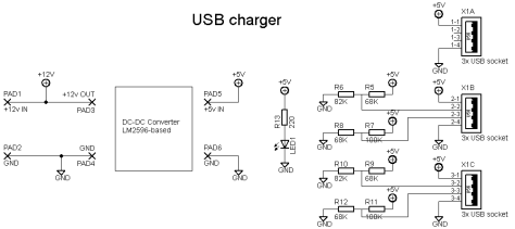
Manufacturers of rechargeable electronic devices have in most cases standarised the input voltage to 5V, hence made it possible to charge the device from an USB port. This makes life easier. One charger to rule them all! This project is basically a voltage regulator which can be supplied from 6-30V DC, and gives a steady output of 5V, up to 3A. The circuit also implements Apples non-standard method to inform the device charging how much current it may draw.
The intention was to use this charger in my solar-powered cabin, which means it will run of a 12V battery. This device will also be very suitable for cars, boats and all other places where DC power is available. By sticking it to a mains transformer, it will be a good home charger as well (just remember to add rectifying diodes and filter caps after the transformer).

This circuit is simple. The heavy lifting is done by a LM2596 based module, which can be had from eBay for approximately a buck. Cheap fun! This little module however, is very useful and versatile. Some important differences between the LM2596 based module and the LM7809 (LM7805 would be the choice for a 5V regulator) used in the guitar effect power supply are that the LM78xx draws the same amount current from the input side that is drawn from the regulated side. This is because this device is basically a resistor that changes it’s value to keep the output at the wanted level. The LM2596 on the other hand is more advanced and uses some clever electronics inside the chip to achieve that the effect loss in the regulator is much lower than the LM78xx. The efficiency is approx. 80%-90%. This makes the LM2596 more similar to an transformer, hence these modules are often called DC/DC transformers.
Long story short, the LM2596 allows me to use less power from the battery in the cabin to charge my phone, than a similar LM7805 circuit would do.

For most devices, it is sufficient to connect +5V to pin 1 and GND to pin 4 on the USB connector. And this is basically what I have done. Unfortunately Apple products will not charge this way. As is described in this article from Adafruit, Apple products require the USB data pins to be set to special voltages to tell the product how much current can be drawn. For this charger, the maximum allowed charging current is set to 1A. Then the D- (pin 2) must be set to 2.8V and D+(pin 3) to 2.0V. This is done by resistors making voltage dividers. Because of lack of space on the PCB, only two of the three USB outputs have Apple support.

The PCB was designed in Eagle (sch brd) and was designed to fit in a small plastic box. I recommend to use single USB sockets. The only reason why I used the 3-port USB socket was that I had it laying around (I probably scavenged it from an old computer motherboard:). The 3-port socket was a pain in the ass to route! The end product however, turned out pretty alright I think. I have tested it by charging a HTC M9, and an Apple iPhone 4G. Both of them charged at approximately 1A. It was interesting to see how the HTC phone started low, but then increased its current draw, like it was feeling how much current it could draw…

After the PCB was ready, and parts soldered on, I mounted the LM2596 module with some 1.5mm$^2$ solid copper wires. I was very pleased with the visual appeal of the unit;)

The unit was put in a plastic enclosure, and I applied a coat of funky sparkly paint. Voila!

PS. Just realized this would be the perfect way to power one or two RasberryPI’s in a car …


Don’t plug two iphone/ipads in! That regulator only supports 3A. Not 4A.
LikeLike